This is default featured slide 1 title

Go to Blogger edit html and find these sentences.Now replace these sentences with your own descriptions.

This is default featured slide 2 title

Go to Blogger edit html and find these sentences.Now replace these sentences with your own descriptions.

This is default featured slide 3 title

Go to Blogger edit html and find these sentences.Now replace these sentences with your own descriptions.

This is default featured slide 4 title

Go to Blogger edit html and find these sentences.Now replace these sentences with your own descriptions.

This is default featured slide 5 title

Go to Blogger edit html and find these sentences.Now replace these sentences with your own descriptions.

Showing posts with label reprap. Show all posts

Wednesday, December 26, 2012

A focus on ABS and a new printer hood (with video clips)

ABS is a tough, impact and temperature resistant plastic. It can be injection moulded and extruded. It has many common uses, from Lego to car bumpers. Being able to print in ABS is an important progression for me in terms of the robustness of the objects I might design, prototype and print.

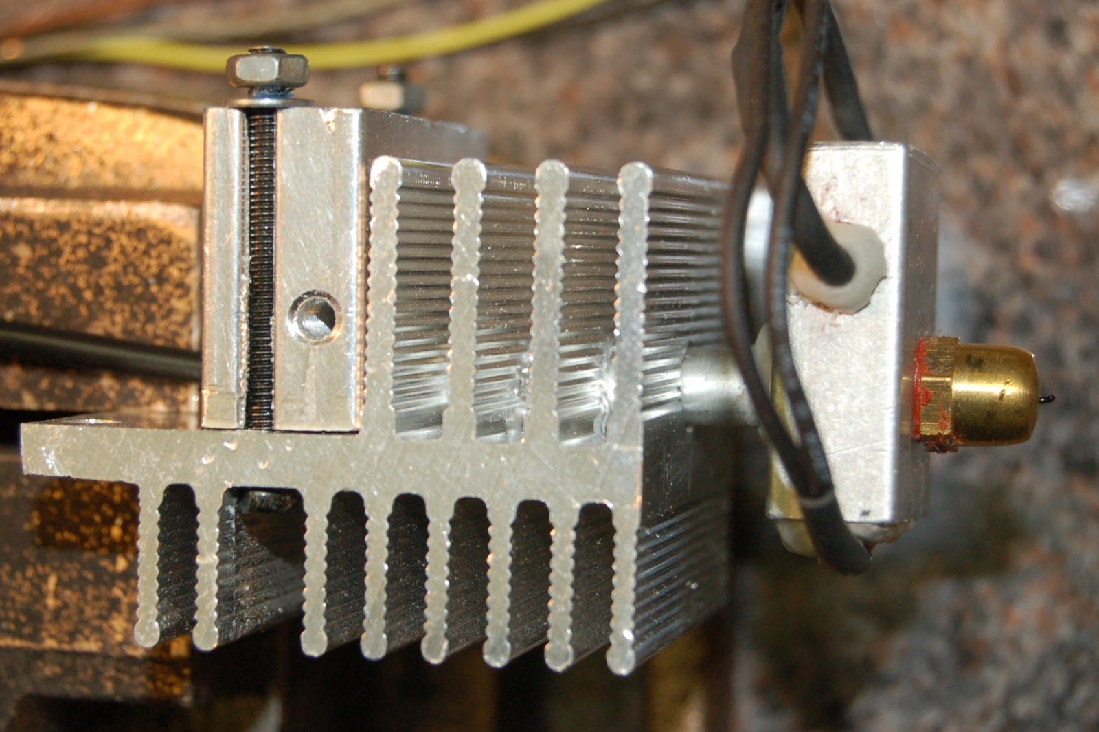
My first ventures into printing with ABS did present some challenges. It's extrusion temperature, in the region of  240 Deg C, is a good deal higher than PLA (185 Deg C). The rising heat from the hot end to my PLA x-carriage was a first concern but the use of an un-ducted fan to cool the underside proved problematic. The freshly extruded ABS was very sensitive to the cooling airflow, causing poor adhesion of the first layer to the print bed. If' you've only printed in PLA you'll find PLA prints better with some cooling, preventing curling, but the first layer of ABS is far more sensitive and does not like stray cooling at all. Fitting a ducting to the fan (light green part visible in photo below) focuses the air flow across the J-head insulator, also keeping the underside of the x-carriage cool. I may eventually print an x-carriage in ABS for peace of mind.

The big addition to my set-up is the hood (see photo). It's a simple box construction made of 6mm MDF and light timber frame. The front has a clear acrylic panel. 

The purpose of the hood is to maintain a steady raised temperature around the printer. I found it levels out at around 28 Deg C at the moment. The printer is located in the garage with a frequently used large door, so heating the whole area isn't practical, and in the winter time the printer extruder and heated bed struggle to get to a working temperature without the hood. The addition of the hood has made a great difference to temperature management in our colder winter months (Ireland). With the hood externally vented it has also eliminated minor concerns about any fumes the ABS might give off if over heated, although I've had to control airflow through the vent to reduce air loss from hot-air convection through that pipe.

Next item to get right for ABS is the heated print bed. PLA is happy with a heated bed in the region of 60 Deg C temperature, and with some PVA coating on the glass bed it will stick well. ABS is a different story. Experimenting by many has resulted with varying guidelines on what temperature is best for the heated bed under an ABS printed part. People seem to have had good success with temperatures ranging from 80 Deg C to 120 Deg C or even higher. This higher heated bed temperature for ABS is required for good initial adhesion and preventing warping as the object grows, but you should reduce the bed temperature after the first layer to prevent wall shrinkage at the base of printed parts. The use of PET tape or ABS juice (ABS/acetone solution) is also found to help adhesion. Some people just ensure the glass is cleaned thoroughly and get very good adhesion straight to glass.

The quickest and easiest way to give a guided tour of my current printer set-up is to post a short video. In it you will see the first layer of the Santa Sleigh being printed. It's being printed with 3mm ABS filament, with a .5mm nozzle at an initial temperature of 240 Deg C, bed temperature of  115 Deg C (approx). First layer is printed slowly but it picks up to about 50mm/s later.

As I move the camera around you will see the host software I'm currently using "Repetier-Host", my wall mounted spools, and the printer electronics, which are now moved outside the box (they need a cover!). Finally, for the keen eye, you will see some timber cross-bracing across the rear threaded rods of the printer. This has enhanced the stability of the unit immensely. My z-rods hang freely from the motors unconstrained. I only use a single trapped z-nut on these rods in each x-end, and no backlash springs.

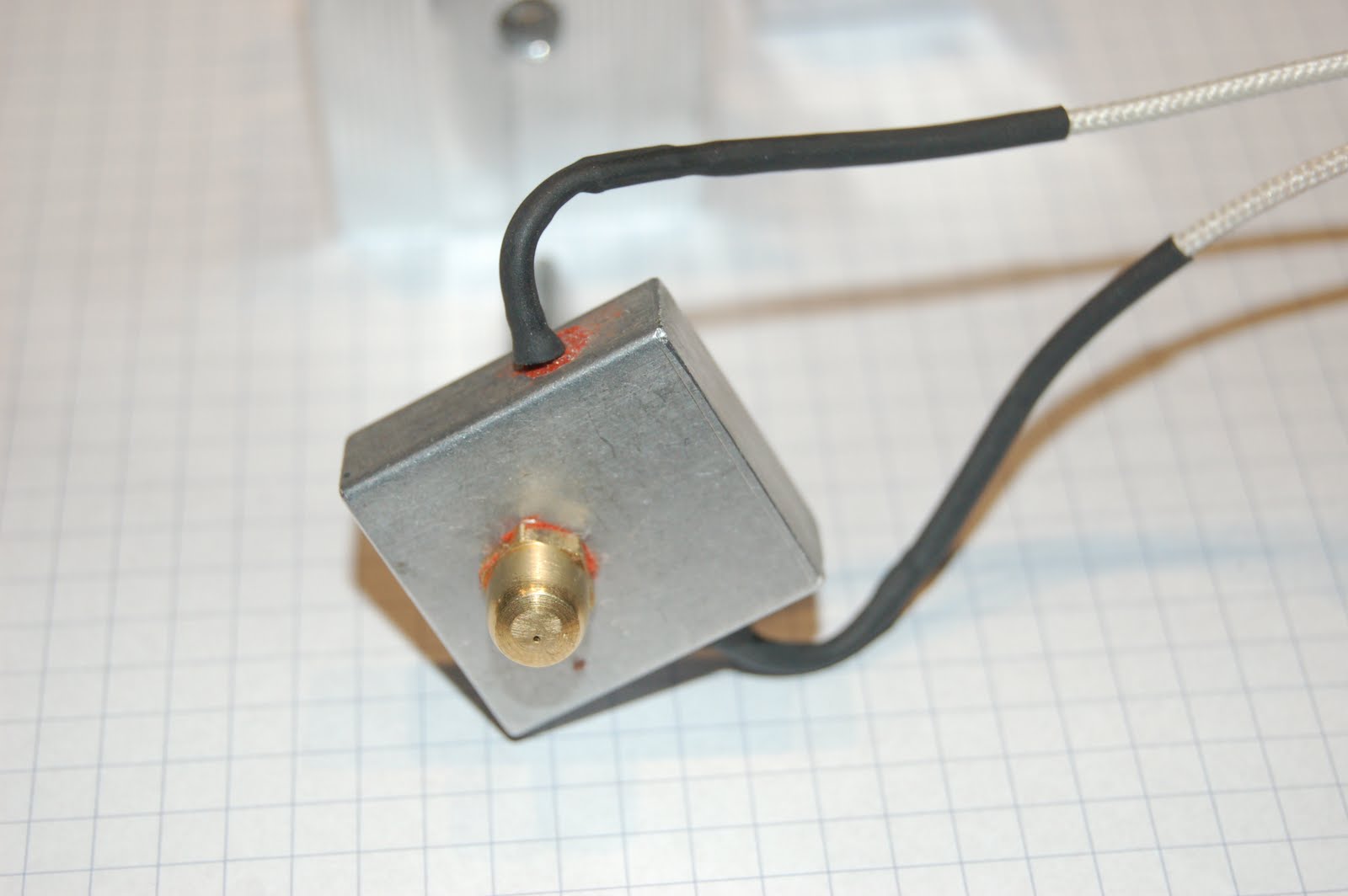
This video clip shows the Santa Sleigh being printed a few layers in (.3mm height/.45width, 25% fill). I've a temporary temperature probe under the heated bed which shows a reading of about 117 Deg C. I expect the surface temperature of the printer bed is a good 15/20 Deg C less. My bed temperature is controlled via a simple circuit (see here). The temperature is set with a variable pot dial. I've various marks on the dial for PLA, ABS first layer and ABS. It's all a bit experimental, but works.


This short video shows the printing of the Sleigh, utilising a time-lapse shot every 20 sec, and a look around the finished item at the end. The printer bed is 200mm x 200mm so you can judge the size of the printed object from that.

Finally for now, here's a clip of the Reindeer being printed. All eight in one go, along with the support struts.

Concluding notes:

  • Printing with ABS has greater temperature management challenges, for both the hot-end and printer bed.
  • The single biggest tip I can give is to reduce the printer bed temperature immediately after printing the first layer of any ABS job. This will prevent shrinkage or distortion of the lower 5mm of the object, a phenomena dubbed 'elephant feet' on the forum, because of the inward deformation of the work around the base. I estimate a reduction in bed temperature of about 20 Deg C is not unreasonable, but I would recommend you experiment to find settings that work best for your own set-up.
  • I've not found ABS parts to be as dimensionally accurate as the same parts printed in PLA. I believe this phenomenon is down to ABS shrinkage. You may want to allow for this in design.
  • The finished ABS product has a smoother feel and any blips or minor stringing is much more easily removed than equivalent imperfections in PLA.
  • While the print resolution is the same, ABS seems to look a lot smoother.
If you have any questions or comments regarding the set-up or operation of my printer feel free to post a comment of contact me via the RepRap forum (http://forums.reprap.org).

Thanks for viewing!

NumberSix.

Sunday, September 2, 2012

Heated bed with three point leveling...

This recent collection of improvements to my printer stemmed from a desire to try some ABS printing, which I haven't actually got to yet. Again a case of one thing leading to another... It needs a higher heated bed temperature (110deg C I believe), and my resistor heated-bed just couldn't achieve those temperatures.

I'm a fan of the three bearing y-carriage. I converted my y-carriage to a three bearing rig a while back (here), but the print bed (upper plate) was still leveled by adjusting four spring loaded screws. When Tony at Think3DPrint3D did a version of the PCB heatedbed that had a support hole in the middle of one edge (see here) I just had to try out an arrangement that had three bearings and only three levelling screws for the print bed.

A heated bed with only three support points would need a support plate that was as large as the bed, but a lot of that support plate would be redundant. I felt it was also best if these three support points were positioned over the bearings for maximum support. The resulting layout eliminates the smaller lower plate in typical Mendel y-carriage designs, but does mean that the y-rods need to be raised to the upper position as the printbed overshoots either end to achieve a full 200mm print area in a Y direction.

This is the new Y-carriage I built:

The carriage is made from 3mm composite sheet material, commonly known as DiBond. It's a plastic sandwich between two light sheets of aluminium. It's very strong and very light. I happened to find some in a black finish. This plate acts as both the mounting board for the bearings and the support board for the heated bed. This simplifies the construction and overall weight of the y-carriage. I used bearing mounts that have been joined by a simple triangle to position them (http://www.thingiverse.com/thing:19771). There's a huge variety of y-carriage bearing holders on thingiverse, some have integrated belt clamps, some without. I just transferred my existing belt clamp and tensioner, and my opto-endstop flag.

The composite sheet material was marked out and cut with a jigsaw, using a fine toothed blade. All the holes were carefully marked and drilled. The three holes to support the heated bed were taped to take M3 bolts, to allow a Nophead style mounting and adjusting method which he talks about here. I also adopted the insulation and cabling method he describes and utilises on his Mendel90 printer. 

Wiring the heated bed: 

The version MK2a (note the 'a') of the PCB Heatedbed has larger soldering tabs as well as the middle hole. Given I wanted to position the middle hole over the single bearing it meant my ribbon cable needed to take a 90Deg turn to position the loop it in the direction of bed movement. The photo above also shows how I soldered on the ribbon cable and attached the thermistor. The exposed contacts were covered with some tape to prevent shorting on the foil insulation which will sit beneath.

I cut a piece of corrugated cardboard and glued on some kitched foil to make an insulator for under the heatedbed.

The foil faced cardboard sits between the carriage and the PCB heatedbed. To secure the ribbon cable I cut a piece pvc tube to protect the ribbon cable from the edges when I used a small buldog clip to clamp it in place. See photo below.
(note the adjustment screw above was not what I settled on.)

The adjustment screws were made up as follows. I took a long M3 spacer nut, thread-locked a headless screw into one end, and cut a screw to fit the other end. (I use a small disc in a Dremel to cut bolts/screws to length.)

I wanted 'soft' washers to pad the lock-screw. The corner of the PCB is quite delicate and I suspect easily broken. To make some PTFE washers, I pushed some PTFE tube through a hole in scrap piece of wood, and used a sharp chisel to cut as many washers as I needed.

Below is a photo of the adjuster screw/nut  It works by loosening the top lock-screw, then turning the long nut to raise or lower the board, then tightening the lock-screw when done.


Here's the newly assembled y-carriage and PCB Heated bed. I cut a piece of picture frame glass to size for initial trials with PLA. I may have to get something better for ABS. There's a bit more work to do before I start into ABS. I want to build a hood and extractor next.


Conclusions:
The bed levelling process is so much easier with only three height adjusters. Start on the right, level front and back, then move to the left centre screw and adjust it until until the bed is levelled in a left/right direction. I level off the print-head tip, and perform the exercise with motors off moving x and y carriages by hand.

Raising the y-smooth rods to their top position only results is a small loss in z-height because the new layout has one less support plate. The original smaller board/plate that held the bearings is no longer required.

The use of Triffid_hunter's bar clamps allowed the rods to sit on the threaded rod, giving a print bed that was almost level before any adjustment. The amount of final adjustment needed with this construction is extremely little.

The whole assembly is much lighter than my previous one. The loss of one board and the introduction of the composite sheet material has contributed to this. The net benefit of a lighter y-carriage assembly is greater print speeds with less strain on the motors or less risk of skipping due to inertia.

That's all for now. Thanks for viewing!
NumberSix 

Saturday, May 14, 2011

Extruder / heater testing...the less scientific way!

Over the past few evenings I've been 'playing with' my newly assembled extruder. I've read many other blogs and studied the RepRap.org wiki, searching for extruder related posts, but there's been no substitute for trying things out myself! I suppose I could have bought more of the components and availed of the collective knowledge gathered by many, and probably been printing away by now, but for me it's also somewhat about the journey!

So... I got my heater/thermistor and stepper motor connected up, after this little interlude, and mounted the assembled unit on a bracket, not on my repstrap, and started testing. I even wired up my little fan. I started up RepSnapper and 'commanded' the heater to commence heating, 40, 50, 60... 80... 100Deg C, on it went. I got brave and punched in 180Deg C, but coax it as I might it would not heat above 140Deg C! What was wrong?

The heatsink is just too efficient it seems, and even with the fan switched off the maximum temperature I could achieve was 180Deg C. I'm sure some experts out there could have seen this coming, and probably also what happened next. Still itching to see what would happen I fed some filament into it (3mm PLA). Not satisfied with hand turning the wheel I kicked the stepper into action and in went the PLA, into the heater. I got a tiny purge of plastic from my newly drilled .4mm hole before the whole thing just stopped feeding. Reversing was also futile. There it stopped to await it's first autopsy! :-)


Reading back through some of the extruder related articles made a lot more sense now. A short as possible transition zone from hot to cool is good. See the guru Nophead's writings on the extruder subject here, and the benefit of a PTFE lining reducing upward heat migration, and smoothing the path downwards, is also manditory you'd feel if you study Adrian Bowyer's most excellent Universal Mini Extruder design. But flying in the face of the need for any PEEK or PTFE, and the long journey from feeder to heater, is the UP! Extruder design, with simple metal pipe linking 'hot-end' to 'cold-end', and not a special plastic in sight.

So where was I going wrong? Examination of the jamed extruder revealed that the idler bearing that applies pressure on the filament so it's gripped by the nobbed feeder spindle, had completely squashed the filament. See photo below.
In switching off the fan to allow the temperature to rise in the heater, the temperature also rose in the unlined feeder tube, causing the PLA filament to soften and be deformed by the idle bearing lateral pressure. The raised temperature in the feeder tube also cause the PLA to deform, expand and jam.

To remove the jammed PLA i had to heat the dismantled assembly slightly with a hot-air gun and the plastic bits pulled right out.

Determined to continue testing the hot-end I next separated it from the heatsink completely, insulated the shaft in with some glass rope and held it in a small vice. (see photo). There was no difficulty in reaching temperatures a high as 220Dec C in this situation. (12v supply to 6ohm resistor in the heater block).


While I'm not sure of the accuracy of current temperature feedback to RepSnapper I can expect it's a pretty good guideline indicator of temperature. Here's what the RepSnapper temperature control/feedback fields look like. You can also see the manual extruder speed/feed control buttons just below the temperature section. There is a 'heater on' green light also on the Gen6 board which is very handy.

And... by manually feeding some PLA I got a nice free flowing extrusion. (see photo below). It took only minimul pressure to feed the filament. The extrusion did curl as it emerged and I did have to pull it straight just to prevent it sticking to the nozzle, but over all a satisfactory result!


Conclusions:
My heatsink is too large for heat output capability of the resistor/voltage.
I either need a more powerful heater, like the UP! has... 24v 80W heat probe, or I need a better thermal barrier between the hot and cold ends of the extruder. That's back to PEEK/PTFE type design.

Some positive points... the extruder stepper, which I salvaged off and old 5.25" floppy drive, the old photocopier cog wheels, the nobbed drive shaft and the idler pressure bearing all worked very well as a feed mechanism!

Thanks for viewing... comments and questions welcome!
?

Tuesday, May 10, 2011

Extruder 'hot-end'...

I've been trying to come up with an extruder 'hot-end' design that doesn't use the expensive PEEK material that is in common use in other designs. My initial thoughts have been to use a salvaged heat-sink, clamping the feed shaft from the hot-end heater, and using a small fan to cool the heat-sink. My experiments over the last few evenings have caused me to question this approach, based on challenges I've encountered during my tests. I think I'll outline my tests in a subsequent post, but for now here are some photos and a general description of my initial hot-end design and construction.
The heatsink and aluminium blocks are all salvaged from some scrap electronics boards. I drilled a 6mm hole to receive an 6mm aluminium feeder tube. It's an 'off the shelf' piece of 6mm tube with a approx 3.5mm hole. (The thermister is not fitted in the photo above.)
I filed the top 12mm of the tube flat on three sides, and cut a square slot to match in what I'll call my clamping block. This aluminium block (salvaged heatsink block) had two convenient slots in it's sides through which I fed two small bolts in order to clamp it to the vaned heat-sink. Here's another view (below) of this assembly in which you can see one of the bolts that clamps the solid block to the vaned heatsink.

My heater is a resistor from Mendel-parts, and a matching thermistor. I secured the resister with high-temp silicone, and wrapped the thermistor in a square of plumbers PTFE tape before inserting into a 1.5mm hole, 4mm deep, a tip I gleened from Adrian's approach documented here.

Here you can see where the thermistor is secured into the block. I added some high-temp glue (used to attach glass rope to stove doors. I had a little left over from another job!). I added some glue to the resistor also. I should use that Kapton tape, but I don't have any at the moment. I think I'll have to order some other bits and pieces soon... building a new wish-list!

The nozzle is a brass cap-nut with a .4mm hole drilled in it. It took some searching but I got some .4mm drills locally (Joe McKennas, Limerick) along with a 'pin vice' from Maplin, also local. There are many great suggestions on the net on how to drill a very small hole, but you know wht worked for me? I put the cap-nut in the vice, dinged and center hole with a sharp nail, then drilled the .4mm hole by spinng the pin vice by hand while applying pressure on the bit. Brass is relatively soft and the tiny drill bit just worked right through it. ( I did try my first .4mm drill in a power drill, catching the pin vice in the power drill chuck, but the tiny bit just snapped like twig - just as well I bought a few.) You should be able to see the tiny hole in one of the photos above. Here I'm using the drill to clear the hole during first extrusion attempt.


That's if for this post. I'll do a little bit on how I got on with wiring and powering it up and some heating experiments, in the next post.

Thanks for viewing!


Monday, May 9, 2011

Extruder "cold-end"...

Here are some photos of my Extruder 'cold-end'. The motor wasn't yet secured in this shot but is now bolted to the base.
The cogs are salvaged from an old photocopier. I realise the smaller cog has typically less teeth in other designs but we'll see how this one goes! The stepper motor is from an old 5.25" floppy drive!

The bearing recesses were achieved by clamping the two 15mm blocks together and drilling a hole 22mm diameter with a flat wood bit to a dept equal to the bearing width, so the bearing would recess until flush with the edge. These recesses hold the bearing snugly in either side of the block.
Here you can see the bearing mounting block for the filament drive shaft, and it's partner, the idle pressure bearing (smaller bearing pinned into the second block.)


This photos shows the nobbed center of the shaft. I nobbed it using an M3 tap following the Wade Extruder instructions. I've used 6mm steel shaft. I cut it to the desired length and threaded both ends and am using M6 nylock nuts on either end. The skateboard bearings came with sleeves which reduce the bearing centers to 6mm, normally an 8mm hole. I'm pinning the large cog wheel with a small bolt through a hole drilled through the shaft.
Here's a photo of my extruder filament drive mechanism components.Everything has been done with minimal power tools, a variety of drill bit sizes, some files, tap and die set, saws and a bench vice. I have some photos of the 'hot-end' which I'll post next.

Thanks for viewing. Comments and questions welcome.?