Over the past few evenings I've been 'playing with' my newly assembled extruder. I've read many other blogs and studied the RepRap.org wiki, searching for extruder related posts, but there's been no substitute for trying things out myself! I suppose I could have bought more of the components and availed of the collective knowledge gathered by many, and probably been printing away by now, but for me it's also somewhat about the journey!
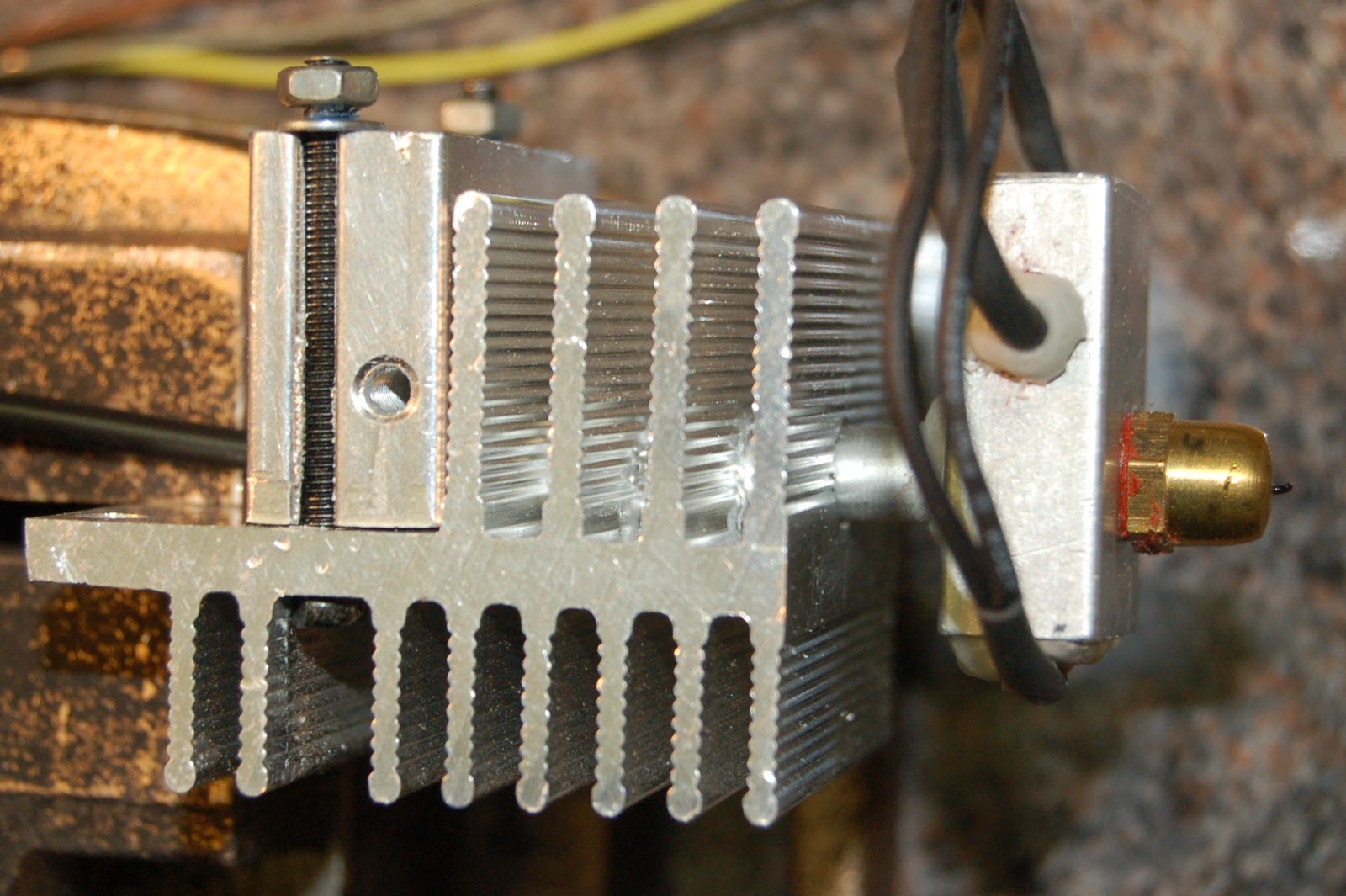
So... I got my heater/thermistor and stepper motor connected up, after this little interlude, and mounted the assembled unit on a bracket, not on my repstrap, and started testing. I even wired up my little fan. I started up RepSnapper and 'commanded' the heater to commence heating, 40, 50, 60... 80... 100Deg C, on it went. I got brave and punched in 180Deg C, but coax it as I might it would not heat above 140Deg C! What was wrong?
The heatsink is just too efficient it seems, and even with the fan switched off the maximum temperature I could achieve was 180Deg C. I'm sure some experts out there could have seen this coming, and probably also what happened next. Still itching to see what would happen I fed some filament into it (3mm PLA). Not satisfied with hand turning the wheel I kicked the stepper into action and in went the PLA, into the heater. I got a tiny purge of plastic from my newly drilled .4mm hole before the whole thing just stopped feeding. Reversing was also futile. There it stopped to await it's first autopsy! :-)

Reading back through some of the extruder related articles made a lot more sense now. A short as possible transition zone from hot to cool is good. See the guru Nophead's writings on the extruder subject here, and the benefit of a PTFE lining reducing upward heat migration, and smoothing the path downwards, is also manditory you'd feel if you study Adrian Bowyer's most excellent Universal Mini Extruder design. But flying in the face of the need for any PEEK or PTFE, and the long journey from feeder to heater, is the UP! Extruder design, with simple metal pipe linking 'hot-end' to 'cold-end', and not a special plastic in sight.
So where was I going wrong? Examination of the jamed extruder revealed that the idler bearing that applies pressure on the filament so it's gripped by the nobbed feeder spindle, had completely squashed the filament. See photo below.
 In switching off the fan to allow the temperature to rise in the heater, the temperature also rose in the unlined feeder tube, causing the PLA filament to soften and be deformed by the idle bearing lateral pressure. The raised temperature in the feeder tube also cause the PLA to deform, expand and jam.
To remove the jammed PLA i had to heat the dismantled assembly slightly with a hot-air gun and the plastic bits pulled right out.
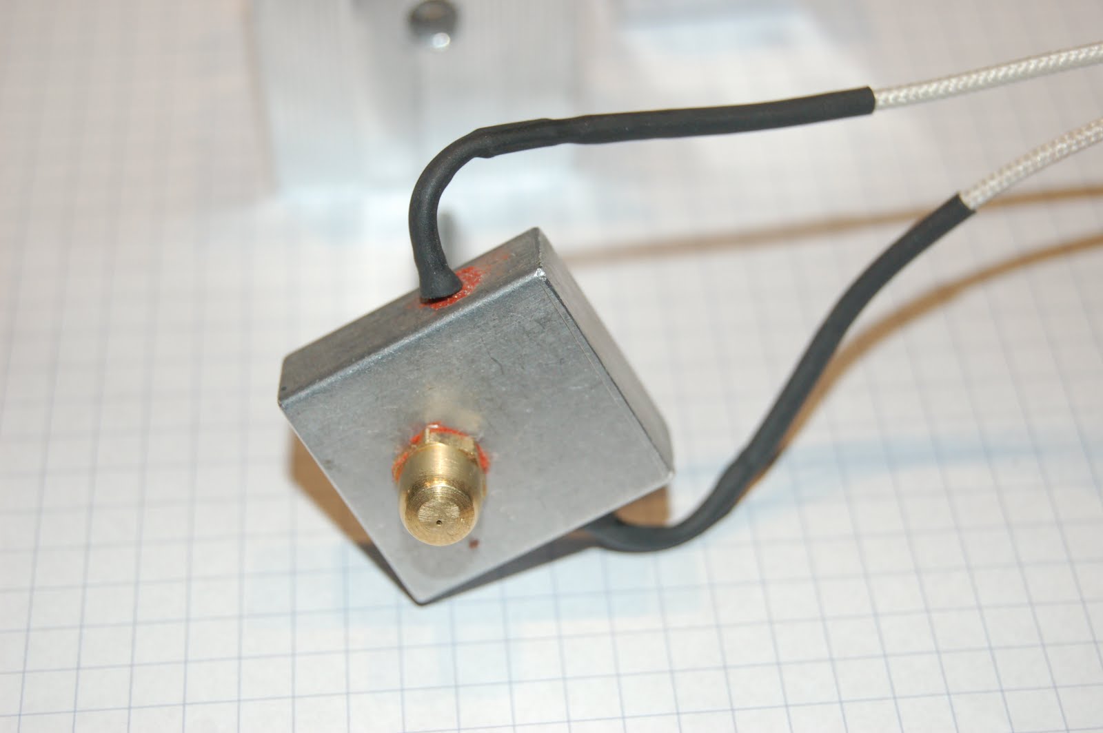
Determined to continue testing the hot-end I next separated it from the heatsink completely, insulated the shaft in with some glass rope and held it in a small vice. (see photo). There was no difficulty in reaching temperatures a high as 220Dec C in this situation. (12v supply to 6ohm resistor in the heater block).

While I'm not sure of the accuracy of current temperature feedback to RepSnapper I can expect it's a pretty good guideline indicator of temperature. Here's what the RepSnapper temperature control/feedback fields look like. You can also see the manual extruder speed/feed control buttons just below the temperature section. There is a 'heater on' green light also on the Gen6 board which is very handy.


So... I got my heater/thermistor and stepper motor connected up, after this little interlude, and mounted the assembled unit on a bracket, not on my repstrap, and started testing. I even wired up my little fan. I started up RepSnapper and 'commanded' the heater to commence heating, 40, 50, 60... 80... 100Deg C, on it went. I got brave and punched in 180Deg C, but coax it as I might it would not heat above 140Deg C! What was wrong?
The heatsink is just too efficient it seems, and even with the fan switched off the maximum temperature I could achieve was 180Deg C. I'm sure some experts out there could have seen this coming, and probably also what happened next. Still itching to see what would happen I fed some filament into it (3mm PLA). Not satisfied with hand turning the wheel I kicked the stepper into action and in went the PLA, into the heater. I got a tiny purge of plastic from my newly drilled .4mm hole before the whole thing just stopped feeding. Reversing was also futile. There it stopped to await it's first autopsy! :-)

Reading back through some of the extruder related articles made a lot more sense now. A short as possible transition zone from hot to cool is good. See the guru Nophead's writings on the extruder subject here, and the benefit of a PTFE lining reducing upward heat migration, and smoothing the path downwards, is also manditory you'd feel if you study Adrian Bowyer's most excellent Universal Mini Extruder design. But flying in the face of the need for any PEEK or PTFE, and the long journey from feeder to heater, is the UP! Extruder design, with simple metal pipe linking 'hot-end' to 'cold-end', and not a special plastic in sight.
So where was I going wrong? Examination of the jamed extruder revealed that the idler bearing that applies pressure on the filament so it's gripped by the nobbed feeder spindle, had completely squashed the filament. See photo below.

To remove the jammed PLA i had to heat the dismantled assembly slightly with a hot-air gun and the plastic bits pulled right out.
Determined to continue testing the hot-end I next separated it from the heatsink completely, insulated the shaft in with some glass rope and held it in a small vice. (see photo). There was no difficulty in reaching temperatures a high as 220Dec C in this situation. (12v supply to 6ohm resistor in the heater block).

While I'm not sure of the accuracy of current temperature feedback to RepSnapper I can expect it's a pretty good guideline indicator of temperature. Here's what the RepSnapper temperature control/feedback fields look like. You can also see the manual extruder speed/feed control buttons just below the temperature section. There is a 'heater on' green light also on the Gen6 board which is very handy.

And... by manually feeding some PLA I got a nice free flowing extrusion. (see photo below). It took only minimul pressure to feed the filament. The extrusion did curl as it emerged and I did have to pull it straight just to prevent it sticking to the nozzle, but over all a satisfactory result!

Conclusions:
My heatsink is too large for heat output capability of the resistor/voltage.
I either need a more powerful heater, like the UP! has... 24v 80W heat probe, or I need a better thermal barrier between the hot and cold ends of the extruder. That's back to PEEK/PTFE type design.
Some positive points... the extruder stepper, which I salvaged off and old 5.25" floppy drive, the old photocopier cog wheels, the nobbed drive shaft and the idler pressure bearing all worked very well as a feed mechanism!
Thanks for viewing... comments and questions welcome!
?