There's such a variety of RepRap part designs out there that you really have to match them up carefully if you plan to upgrade any individual aspect of your printer. You can 'pick 'n' mix' but as I've learned you should think it through and double check everything before starting in to an upgrade. Here are some examples of the minor issues I bumped into when I bought a new extruder hot-end, the
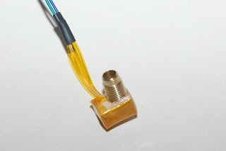
J-Head IV-B.
The j-head has a 16mm diameter insulator (the black PEEK cylinder). You have to find some way to mount the insulator to the extruder body. There are many options. There are various mounting plates available to fit the notch, and then bolt the plate under the extruder, but the top of the insulator must still insert into the extruder. My
existing extruder only had a 12mm hole in it's base, so I had to print a new extruder. I had a look around and decided I'd try
this extruder (Jonas Kuehling's version of Greg's Wade extruder). Jonas has a variant with a 16mm hole in the base, and holes to bolt across the insulator notch.
So I had to print a new extruder. To save effort (so I thought!) I'd transfer the hobbed bolt and recently printed herringbone gears from the extruder I was removing, but I soon found more complications. The combination of
Triffid_Hunter's Herringbone Gears, my hobbed bolt and Jonas' extruder just wouldn't line up. The hobbed notch wouldn't align with the filament guide hole and there was not enough travel for the motor to close the small gear fully against the large gear! I should have just reassembled the old extruder at that point and printed Jonas' gear set that did match, but no, nothing like a challenge! :) A second printer would be handy!
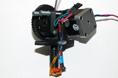
I reversed the hobbed bold and put the nut and a lock-nut on the large gear side allowing adjustment and perfect alignment of the hobbed bolt to the filament. I fitted a spring on the other side to keep some tension on the bolt. Between the filament in the notch and the meshing herringbone gears there is actually little incentive for the hobbed bolt to drift horizontally anyway. Here's a photo or two of the current hobbed bolt arrangement! It's been running like this for a few weeks without issue.


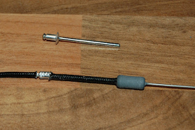
Securing the hot-end insulator: The insulator pushes into the extruder base and a common way of securing it seems to be with two M3 bolts through the holes in the extruder and across the notch in the insulator. You may have to pre-drill, glancing the insulator notch to get those bolts to fit. I'm not familiar with the mechanical properties of PEEK. It feels extremely hard and tough. I figured a 3mm drill meeting it at an acute angle would just bend away into the plastic so I took an alternative approach to securing it. I made a simple pin from coat-hanger wire, rounded the tops with a small file and pushed it in with a small clamp (photo below).
It's a tight fit and hold the insulter amazing well. There's no movement in the hot-end. I'm printing for weeks with this securing method and the hot-end/insulator remains securely attached.
I added a little bit of PVC tube to the pin to gently secure the wires rising from the hot-end. The pin can be removed with a wire hook and a firm pull.
Oh... the poorly meshing gears due to mismatch of gears and extruder... I elongated the motor mounting slots with a round needle file and motor now travels close enough for the gears to mesh perfectly. Not idle, but it works!
BTW - here's a photo of all the components that went in to the new extruder.
General comment on extruders: Once you have your printer running smoothly, there is little enough call for the quick-release mechanism on the idler-bearing, and indeed if you've clogged up the hobbed bolt badly the best way to clean it is to remove the bolt. Also, some have felt the need, including me, that a top filament guide is necessary in the design, leading to the return of a top guide.
This brings me to the argument that Nophead presents for the
Wade's style extruder. If you use a spring in conjunction with a regular nut on the hobbed bolt then the nut won't loosen, but can easily be removed if you need to inspect or clear the hobbing. Also, if you have got your idler spring tension just right, the last thing you want to be doing is backing the bolts off to remove the idler. If you aren't removing the idler, then four securing bolts makes little odds over two bolts and a hinge, and in some ways makes for a more evenly pressured idler.
I printed
it out (photo above) and will fit it out and try it at some point. (I've thickened the base so I can fit a larger gear and have it clear the x-carriage. An interesting side-effect of thickening the base is it gives even more robust support to the 16mm diam insulator, but I would caution that you need significant active cooling on the hot-end insulator if you are going to mount it directly in to a PLA extruder. Another clever touch to Nophead's variant is a circular recess at the inner most end of the 16mm hole. This allows the insulator to seat perfectly into the extruder base without any clean-up of the hole. (You'd have to be there to appreciate that detail fully! :) )
Since I'm on 'extruders' I'd also like to highlight this set of RepRap design reworks by the guys at
EckerTech, which includes an
interesting take on the extruder. Their extruder design features, hinged idler with no hinge bolt, a single compression bolt on the idler with no spring (good argument for using a washer presented), and a motor that rotates about one mounting point to adjust rather than sliding! Nice work, and they mention in their forum that they plan to publish their designs once they are finished tidying them up. Nice work.
As always, thanks for viewing. Comments and questions welcome!
Regards,
NumberSix


