This is default featured slide 1 title

Go to Blogger edit html and find these sentences.Now replace these sentences with your own descriptions.

This is default featured slide 2 title

Go to Blogger edit html and find these sentences.Now replace these sentences with your own descriptions.

This is default featured slide 3 title

Go to Blogger edit html and find these sentences.Now replace these sentences with your own descriptions.

This is default featured slide 4 title

Go to Blogger edit html and find these sentences.Now replace these sentences with your own descriptions.

This is default featured slide 5 title

Go to Blogger edit html and find these sentences.Now replace these sentences with your own descriptions.

Wednesday, June 20, 2012

Herringbone gears make a difference...

Quick Update: Herringbone gears are 'the business'!  I fitted my newly printed herringbone gear set ( http://www.thingiverse.com/thing:10707) to my existing extruder and I saw an immediate improvement in print quality on a repeat print of the Dual Spiral Lightbulb. It was worth the effort. The basic difference the new gear set made was much improved control of retract/restart, which are frequent on this type of print. There was a quicker restart of flow as the print head moved position and less stringing for the very same gcode file!


The gears were easy to replace. I had no adjustment to make. I didn't even remove the extruder motor. I removed the hobbed bolt and fitted it to the new large gear and transferred the locknut to the small one, assembled and away it went. The new gears printed so cleanly I had no clean-up to do at all. I gave them a little bit of PTFE spary and they meshed perfectly, smooth and quiet.


The 'reprint' test, shown in the short video clip is the exact same gcode file that was used to print the piece shown in the previous post. By running the same gcode it allowed me to do a direct comparison of the difference the new herringbone gears made. This version has a fuller body to the tenderals and less stringing. I'm very pleased with the result of the change. I can now fine-tune my retract settings with more confidence!

Thanks for viewing!
NumberSix


Sunday, June 17, 2012

Quality review...

Recent disappointing efforts to print some smaller delicate objects, specifically the competition piece "Dual Spiral Lightbulb" left me thinking long and hard about where the quality issues lay in my printer. Was it software settings? Were there mechanical issues? Up until this point I had growing confidence that my printer was capable of 'good' quality prints, but the challenges posed by spindly objects, caused me to question that assumption. What might be causing my print quality issues? What could I do about it?
Above is one of my many unsatisfactory attempts to print the "Dual Spiral Lightbulb". The example in the photo was probably my 'best' one, but suffered failure as it concluded, when the nozzle grabbed the top, then ripped the print off it's base as the nozzle parked up.

I struggled to reduce stringing, ooze, and 'plastic-starved print continuations'. No matter how I'd set the Slic3r retractions/restart lengths, extruder speed, etc., I couldn't find a balance, or even achieve consistency. I even tried out KISSlicer and it's equivalent settings (Suck/Prime and De-string Speed) but to no avail.

My extruder hot-end (1.75mm/.35mm) has a long melt-chamber. It's by now an old-style M6 threaded brass design, with a long 2mm hole from well above the heater block, to within < .5mm of the nozzle. This has to be partially to blame as it introduces an undesirable length of 'spongy' plastic between the firm retracting plastic filament (PLA) and the nozzle tip. It may also absorb the downward motion of the feeding filament as printing restarts. This, on it's own should have been possible to accommodate with software compensation, but I struggled to achieve good results after hours of software tweaks. I felt there were more issues at play.

I found there was quite a bit of backlash in the cold-end gears. I had tightened the gap between the two gears by moving in the motor but re-examining it, I don't think the motor held it's position. So I concluded the general quality of that gear set was too poor for my demands and it was time to print a new set!

The Herringbone Gear Set was my new choice. I printed them in PLA with the .35mm nozzle and .20mm layer height, and a careful speed of 30mm/sec, giving an excellent quality print. The quality of this print restored some of my confidence in the printer!


The smaller gear failed to slice in Slic3r, giving an "overlapping or self-intersecting facets" error. As an exercise I had a go with KISSlicer, learning how to match the layer, speed and other settings as I went along, and successfully sliced the smaller gear. KISSlicer has a very impressive interactive visual rendering of the object and slicing process, and allows close inspection of the model and print path in a three dimensional representation. It is a commercial software package, but even the free version is worth a look. 


Will all the test printing in the last week I found it very handy to add some additional buttons to Pronterface. It's easily done, and very convenient to have a pre-set buttons to hand to increase/decrease 'speed' or 'extrusion flow rate', with a simple line command of M220 SXXX, or M221 SXXX executed by the appropriate button. The M220 and M221 commands allow you to make live changes to current print and observe the effect, instead of having to quit out, adjust and regenerate the gcode. Custom buttons highlighted below.

The small gear, shown beside it's companion below, was printed at a slower speed of 15mm/sec perimeter, with .20mm layer height, again with the emphasis on print quality rather than speed. It was sliced with KISSlicer.

Next steps will be to fit the new gears and see how they work!

Thanks for viewing! As always, comments and questions welcome. I'm always contactable via the RepRap forum.
Regards,
NumberSix


Saturday, June 9, 2012

Voronoi D Tower attempt...

I gave a shot at this weeks forum competition , the Voronoi D Tower, but failed to complete a full print. Examples of some failed attempts in photo below.
I'd keep getting to a height of about 30mm then the print would separate from the heated bed. It was frustrating and time consuming. The headed bed had been working excellently from original set-up a while back, with printed pieces of all heights sticking well to it, and then clicking right off when it cooled. I'm puzzled but will continue to ponder it! :(


Sunday, June 3, 2012

Headset cable repair

(Quick Post) The cable on my son's headset got a tug and broke recently. They would be his favourite headset, and the latest fashion, so the 'repair' challenge was taken up! I soldered the tiny wires together, but I needed to devise some kind of junction box for the new joints. Here's what I did...

I drew out the little junction box is SketchUp, incorporating the headset logo. (I've duplicated and flipped it above just to show the logo, but you only need one box, printed twice.).

I printed two copies, in a colour that matched his headphone cable.

I glued and clamped the two halves together, securing the joint between the round and flat cable. I coloured the logo with a pen. (Some day I'll have dual extruders so I can print in two colours! )

That's one less item on the repair shelf! :)

Friday, June 1, 2012

"Sappho's Head" competition submission...

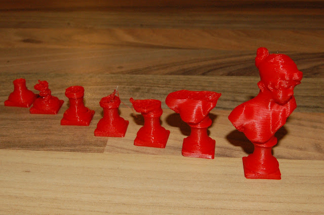
I put an entry into the Weekly Print Competition taking place on the RepRap Forum. It was a great learning experience to enter something like this and brought the standard of my printing on immensely. The biggest challenge for me in printing this little object was to develop a good approach to cooling. Here's the final print I submitted, and some detail on the process.
It only stands 54mm high in reality, and quite a challenge to print. The STL is on Thingiverse if you want to give it a go. My Slic3r settings were as follows:
; generated by Slic3r 0.7.1 on 2012-05-29 at 22:59:22
; layer_height = 0.25
; perimeters = 2
; solid_layers = 2
; fill_density = .15
; nozzle_diameter = 0.35
; filament_diameter = 1.74
; extrusion_multiplier = 1
; perimeter_speed = 15
; infill_speed = 30
; travel_speed = 130
; extrusion_width_ratio = 0
; scale = 1
; single wall width = 0.39mm

Here's a view from a different angle...

The biggest challenge I faced was cooling the print as it was printing. The iterations of my cooling process development are well illustrated by the many failures I had before I finally printed the object successfully.


My particular 'home-brew' hotend is difficult to keep hot at the best of times, so when I was faced with having to blow cool air on the object being printed it was robbing heat from the heater block faster than the resistor could generate it. Many forms of directs fan arrangements failed. I printed a few of the cooling duct solutions found on Thingiverse, but eventually finished up with a highly modified version of one of those ducts I based my fan duct on the lower part of this design. It actually failed after the lower section (due to lack of cooling!) so I completed the mock up with cardboard and hotmelt glue, and some light metal sheet I had. To get on with the job quickly I simply hot-melted the fan duct to the x-carriage.

Here's a photo of my 'hack job' cooling solutions.

It had vents exiting directly downwards (seen hear from beneath, via the mirror printbed), but I closed those vents off, and used a heated nail to punch a series of holes in the inward facing walls of the duct. This directed air very specifically on to the freshly printed work area, and gave focused cooling. It also minimised cooling of the hot-end.


I had to add additional insulation to my hotend to minimise heat loss from the cooling process. I used strands of glass rope wrapped around the nozzle. My hotend already has a PTFE jacket!

Here's a short video clip of the final stages of the Sapphos print...


Thanks for viewing!
NumberSix