This is default featured slide 1 title

Go to Blogger edit html and find these sentences.Now replace these sentences with your own descriptions.

This is default featured slide 2 title

Go to Blogger edit html and find these sentences.Now replace these sentences with your own descriptions.

This is default featured slide 3 title

Go to Blogger edit html and find these sentences.Now replace these sentences with your own descriptions.

This is default featured slide 4 title

Go to Blogger edit html and find these sentences.Now replace these sentences with your own descriptions.

This is default featured slide 5 title

Go to Blogger edit html and find these sentences.Now replace these sentences with your own descriptions.

Sunday, November 27, 2011

Look... no fender washers! (608 bearing Idler hub)

With feedback to my previous post suggesting stationary fender designs of any kind were really the wrong direction to be going to reduce belt friction, I "bit the bullet" this evening and went to work on proper hubs for my idler bearings! Here's one of my new idler hubs now fitted to my y-axis. You'll notice the absence of the large fender washers, and I'm glad to see the back of them! :)


I began by reviewing the existing designs such as this one: http://www.thingiverse.com/thing:503 and this one: http://www.thingiverse.com/thing:3970 and even printed some of them out, but didn't like them so I devised and sketched a split hub design, did some test prints to hone in the dimensions and then knocked out a set...


I used the "Multiply" function in Skeinforge to print multiple matching pairs. Then added a dab of adhesive to the inside and clamped them up sandwiching the 608 bearing in the middle.


And here you go... a set of three idler bearings with hubs!

Backing out the threaded rods to remove the fender washers and fit the new hubs to the printer wasn't as big a job as I thought. My printer is screwed to a baseboard so nothing could move very far when I removed the threaded rods. Here's a view of the newly fitted bearing hub from a different angle. The small washers and nuts grip the center hub of the bearing, and the other rim and printed hub are free to rotate smoothly with the belt.
What has struck me is how quick and easy it has now become to devise and evolve a solution, with the combination of a simple drawing package (Sketchup) and the 3D printer at hand!

(I'll throw the Sketchup file for the hub design up on Thingiverse in a while. There are many hub solutions, even similar to this one I expect, out there, but no harm is sharing this one also.)

Regards,
NumberSix

Saturday, November 26, 2011

Belt fender and other ideas...

The traditional Mendel design has large stationary metal washers (fender washers) on either side of the 608 bearings keeping the drive belts on the bearings. The problem many people have experienced with this arrangement is the belt can rub and grip on the washer, causing resistance and leading to motor step skipping, that can ruin a print job.

Despite spending a lot of time aligning my pulleys with the belts on both the X and Y axes, ensuring my stepper power is set to an optimum level, and checking the carriages are running smoothly on their rods, I've still occasionally had the motors skip.

It's as much an experiment in 'design and print' as anything but I devised a clip-on T-bar that keeps the belt aligned on the pulley with minimum resistance. It can also be retro-fitted without removing the bearing.


?Sketchup is proving an invaluable tool for a quick 'idea-sketch-print-modify-reprint' way of working. I went on to evolve the 'retro-fit' T-bar concept into the following design (below)... but it's heading back to the washer type solution which I'm trying to avoid. Ultimately, I may just have to strip out the bearings and fit proper rimmed sleeves to the bearings. But for now I'm happy to play with different ideas and possible solutions.

  
You can see the above design in use on my Y-axis, at the motor end of the printer (see photo below... excuse the working chaos!). Not sure it's any better that the washers, but again, it can be retro-fitted without removing the bearing, and it has less contact surface with the belt, and is a slipper material.


By the way... My acrylic sheet had lost it's grip. I couldn't get the first layer to take to it at all. I tried the blue tape but couldn't get plastic to stick to that if I paid it! (no heated bed yet). So I flipped my acrylic sheet (12mm plate - salvage) over and continued on the under-side. I print the first layer really close to the ground to force it onto the surface and it takes nicely. It does leave a lip around the base of the printed objects but that's not a problem for me at the moment.

I discovered later that a quick wipe of white spirit cleans the acrylic surface nicely and renews it's willingness to hold down the first layer. I still have issues though with larger objects which lift at the edges as the object cools. I do need to get a heated bed. I'm looking into the options.

In the interim, there was an idea on Thingiverse that adding 'mouse ears' to your design could help keep it stuck down to your print bed, if you didn't have a heated print bed. I had to try it out, and it seems to work. See the 'mouse ears' I added to the object in the photo below. That illustrates what I'm talking about.
The object is a replacement 'quick release tripod plate'. (It attaches to the base of you camera and attaches to your tripod... unless you loose it, and have to design and print another one! )
Here's the finished item... I'm delighted with the print quality and turn-around time on these one-off items!

The above exercise was a modified derivation of a plate componend of this item: http://www.thingiverse.com/thing:13184 I imported the plate.stl into Sketchup, increased the height so my longer blot would fit, and made it wider so it sat better into the receiver.

(Technical note: Nozzle .35mm, Layer Height (mm) .25, Extrusion Width (mm) .45, speed 40mm/sec, 20mm/sec on perimeter, Pronterface/SFACT.)
As always... questions and comments welcome, and happy printing!
NumberSix

Sunday, November 6, 2011

"We can rebuild..."

"We have the technology... we can rebuild..."
It's more like "spot the difference" really, but regular followers will observe that the transition from wood to plastic has commenced. I've replaced my wooden x-axis components with newly printed plastic (PLA) ones. As I've become more fussy about print quality I've realised a little looseness here and there, and tiny wobbles in the z-rods were showing up as patterns in my printing. I've printed quite a few components for a complete new RepRap at this stage, but with the accuracy of some components now being impacted I chose to do an interim rework of my repstrap.

It's got a new x-end idler. This one http://www.thingiverse.com/image:63587, but instead of fitting real LM8UU linear bearings, I've fitted these printable PLA substitutes http://www.thingiverse.com/thing:12238. We'll see how that experiment goes!
Now, just to mix it up a bit I've put the more traditional x-end motor bracket, http://www.thingiverse.com/image:63177, on the far end, but I've modified it slightly. I'm only using one nut on the z threaded rods. Can't see the point of the second nut and the spring between them. I know it's an anti-backlash design, but I've had only one nut in my wooden design and gravity looks after backlash in the vertical direction. I've no plans to print in zero gravity. :-) Also I couldn't bring myself to use that overhanging motor design, so my motor stays inboard for a more balanced look.

 Final update worth a mention has been my move to printed z-rod couplers, the symmetric ones... http://www.thingiverse.com/thing:11220. I had a steel rod coupler, seen here, but was so rigid it exaggerated imperfections in the threaded rod, resulting in motor and x-axis wobble. The new arrangement is much more forgiving and visibly smoother as the x-axis assembly moves up and down.

I've retained my wooden z-motor brackets and vertexes(?). They are solid and accurate.
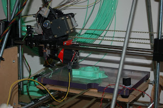
The x-carriage and extruder is now fully RepRap, and as you can see from the part on the bed, I'm printing a spooler!

But a key part of improving print quality has been a fresh examination and fine tuning of basics like squareness, perpendicular z-rods, frame triangle distances all equal. I've screwed the unit to a base board to increase rigidity also. Finally, the introduction of better belt-tensioning technique such as found on Gregs x-carriage, and this little unit (http://www.thingiverse.com/thing:10274) have been invaluable in removing print quality issues due to backlash. The use of these fine tuners allows belt tension to be adjusted a little at a time without over tightening, that might strain something else out of alignment.

Here's a quick look at two test pieces fresh off the newly rebuild rig. I'm pleased with the current print quality.


Now to make it go faster! :-)

Happy printing!
?

Wednesday, November 2, 2011

More extruder improvements...

My extruder design has evolved some more... The last iteration (seen here ) worked quite well, but would succumb to jamming after a few hours of printing. After having to dismantle it once too often it was time to think things out a little further. Here's my latest construction, and some detail on the changes I've made.
Latest extruder iteration pictured above, printing a set of PLA bushings for a friend.

Pict (above) showing most of the components making up my latest hot-end construction.

I identified some issues with the previous design that were addressed in the new version. Here's some of the issues I encountered.

Heat migration upwards through through the stainless pipe was taking place over longer print runs, despite the cooling fan and small heat-sink. When I increased the cooling (larger fan, closer to heat-sink) the hot-end could not reach it's target target temperature.

The heating of the stainless tube and subsequently the PTFE liner and filament was leading to an expansion of the PTFE and softening of the filament, too far from the hot end. It would loose it's rigidity, expand, even buckle and eventually jam.?

I didn't want to have to go down the road of a more powerful heater, so I chose to address it from a different angle. I made some basic changes...
a) I narrowed the neck of the stainless tube just above where it meets the brass. This reduced the cross-sectional-area of the tube, reducing the heat bridge, and made a most amazing difference reducing the heat migration rate considerably. This was evident by a faster time to target temperature, due to less heat loss, and the cooling fan was now able to keep-up with cooling the stainless tube, while the heater block easily maintained targer temperature.

b) I cut off some of the upper portion of the brass nozzle, reducing contact area with the stainless steel.

c) I threaded the ss tube fully, drilled and tapped an aluminium block, and fitted some salvaged heat-sinks to the block. This is a bit over-kill in terms of extracting heat from the ss tube, but it does work well, and takes just a little air flow from the fan to keep everything cool.

d) A final problem I experienced, worth mentioning, was the PTFE liner tube moving within the stainless tube. If the PTFE moved away from where it met the brass, the soft PLA would enter that gap, and would eventually cause a jam. My observations are that PTFE expands and contracts significantly with changes of temperature, and this expansion and shrinkage, especially with the length of PTFE I'm using, is problematic. (I can see myself moving towards a fully stainless solution soon - no PTFE liner).

With the PTFE expanding due to heat migration upwards, I also found it pushed out of the top of the ss tube, so I devised a better way of capping the tube, to hold the PFTE in the tube. this is the purpose of the domed cap-nut you see in the photo above, and also below from a different angle.


Here's another photo of the domed nut which caps the ss tube, holding the PTFE liner in place.


I drilled a 2mm hole in the top of the domed nut. Also visible here is the much reduced and newly shaped aluminium plate, which is shaped to slot into my new x-carriage (I'm now using a "Gregs LM8UU X Carriage" ). The domed nut slots nicely into my extruder cold-end which is a "Gregs hinged accessible extruder". I printed that also, so it's been an amazing process printing enhancements! It just gets better and better! :-)


With the extruder fitted and working nicely, I then went on to print a better fan ducting, that would attach nicely to the x-carriage. Rich obliged by sharing his design... Here's my printed version.


That's it for now. Happy printing!